Channel Master CM-5020 Spécifications
Naviguer en ligne ou télécharger Spécifications pour Antennes de télévision Channel Master CM-5020. Channel Master CM-5020 Specifications Manuel d'utilisatio
- Page / 68
- Table des matières
- MARQUE LIVRES
- SAILOR RT5022 VHF DSC 1
- SAILOR RT5020 VHF DSC Duplex 1
- Introduction 3
- Training Information 4
- Quick DSC distress call 5
- (only for emergency use) 5
- Mayday procedure 5
- Your VHF at a glance 6
- (RT5020/RT5022) 6
- Contents 7
- 1.1 Powering VHF 9
- 1.5 Speaker volume 10
- 1.6 Earpiece volume 10
- 1.7 Squelch 10
- Activating replay 11
- 1.11 Dimming 12
- 1.12 Contrast 12
- 2 Basic DSC operations 13
- 2.3 Transmitting DSC Calls 14
- 2.4 Call a ship station 14
- 2.5 Call a shore station 14
- 2.7 Call a group of ships 14
- 2.8 Create emergency calls 15
- 2.9 DSC call log 15
- 3 Your VHF in detail 16
- 3.4 Setting channel mode 17
- 3.5 Private channels 17
- 3.6 Duplex channels 17
- 3.8 Transmitter power 18
- 3.9 Channel scanning 19
- 3.10 Creating scan tables 19
- 4 DSC operations in detail 20
- 4.2 Group MMSI number 21
- 4.4 Working channel 22
- 4.5 Contact list 22
- 4.5.2 Show contact 23
- 4.5.3 Adding a new contact 23
- 4.6.1 Special calls 24
- 4.6.3 Automatic channel shift 25
- 4.7.1 DSC transmission 25
- Transmit Station Call 26
- MMSI: 001234567 26
- <Menu/back 26
- 4.8.1 Idle display 27
- 4.8.3 Language 27
- 4.8.4 Privacy talk mode 28
- 4.10 Automatic conditions 29
- 4.11.1 Radio software release 30
- 5 Errors and warnings 31
- Fuse 15A ATO 32
- 5.2.2 Self-test 32
- 5.2.3 GPS 33
- 5.2.4 Accessory connection 33
- 5.2.5 DSC routine testing 33
- 5.2.6 Missing MMSI 34
- 5.2.7 Radio time 34
- 5.2.8 Channel not free 34
- 5.2.9 Device failure 34
- 6 Menu tree 35
- 7 Optional functional devices 37
- 7.1.2 Operation 38
- 7.1.3 ON/OFF 38
- 7.1.4 Channel selection 38
- 7.1.5 Volume 38
- 7.1.6 Squelch 39
- 7.1.7 Dimming 39
- 7.1.8 Receiving a DSC call 39
- 7.1.9 Muting alarms 40
- 7.1.10 Transmitter power 40
- 7.1.11 Replay 40
- 7.2.1 Distress initiation 41
- 7.3 Printer 42
- 8.1 International channels 43
- 8.2 US channels 44
- 8.3 BI channels 45
- 8.4 CA channels 46
- VHF with mounting bracket 47
- Mounting option Drilling plan 48
- Drilling plan 48
- Handset for transceiver 49
- Installation 50
- 9.2 Compass safe distance 53
- Connection box board 639121 55
- Extension board 639123 55
- Cable connection diagram 57
- Interfaces 58
- Sparc II Connections 58
- 9.5.1 Antennas 61
- 9.5.2 RX/TX antenna 61
- 9.5.3 DSC antenna 62
- 10 Technical specifications 63
- Thrane & Thrane A/S 68
- [email protected] 68
- www.thrane.com 68
- B5022GB0 Issue: L /09 02 68
Résumé du contenu
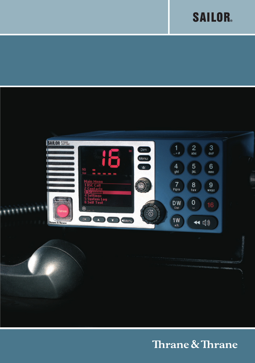
SAILOR RT5022 VHF DSCSAILOR RT5020 VHF DSC DuplexOPERATION MANUAL
4Basic05446. Switch to the new channel – for example, channel 71– and begin your conversation. Press PTT only when you are talking. If you are on asim
5Basic1.8 Channel selectionThe system is defaulting to channel 16 after a normal power-on.Channels can be selected using the(increasing to next valid
6BasicWhen releasing the replay button the replay function will take over the audio system andstart to replay the last XX seconds of data received on
7Basic05442 Basic DSC operationsWhen switched on, your VHF automatically monitors channel 70 for incoming DSC calls.2.1 Menu operationTo operate DSC f
8BasicIf you are busy you can choose to handle the call a little later (e.g. by pressing ),which will stop the alarm sound.When you are ready to acce
9Basic2.8 Create emergency callsIn the category of emergency calls (1.4) you will find thefollowing menu:Emergency1.42 Compose Urgency5 Compose Distre
10Detail3 Your VHF in detail3.1 Abnormal power-downIf for any reason the main power disappears for a period less than 10 minutes, the VHF willbe able
11Detail3.4 Setting channel modeThe VHF is delivered from factory with both Int. & US channels enabled for selection fromthe operation menu.Provis
12Detail3.7 ATIS (inland waterways only)ATIS is mandatory to use in inland waterways on e.g. the Rhine. ATIS is a digital datastream containing ships
13Detail3.9 Channel scanningScanning is an extension to the dual watch functionality, by which it is possible to watchmultiple channels. It is possibl
14Detail4 DSC operations in detail4.1 MMSI NumberTo operate VHF with DSC the equipment needs to be configured with vessel’s MMSInumber. If not configu
15Detail4.2 Group MMSI numberIf the VHF radio is configured as member of a group(s) it will receive group calls addressedto that group.The VHF can be
16Detail4.4 Working channelA working channel will always be suggested by the system if a ship station or group is calledfor a routine call. The workin
17Detail• If the MMSI number is a group number, the group call flow is entered from thewindow where a channel is selected.• If a ship station number M
18Detail05444.5.4 Editing the contact listAny contacts from the list can be edited using a similar principle as described above usingmenu item 2.4.4.5
19Detail4.6.3 Automatic channel shiftThe VHF can be set to automatically changing the working channel on receipt of thefollowing call types:• Individu
20Detail4.7.3 Verification of a DSC call before transmissionThe final step in each DSC call sequence is the verification window, in which it is possib
21Detail4.8 Radio configuration and settingsThis section describes the configuration and settings possible to control from the operatorfront panel and
22Detail• When turning off the VHF using the button, the VHF - for regulatory reasons-will power up in the default language (English) mode when aga
23DetailThe scrambled call can be set up immediately between two RT5022/RT5020, if both arehaving the scrambler application enabled (scramble pin code
IntroductionCongratulations on your new SAILOR RT5022/RT5020 VHF.SAILOR marine equipment is specially designed for the extremely rugged conditions onb
24Detail4.11 Software releases4.11.1 Radio software releaseThe RT5022/RT5020 running software version can be read out from menu 4.6.1.1. Theversion in
25Detail5 Errors and warningsErrors and warnings are shown in the display accompanied by the sounds shown in thefigure below:1 sec.8 sec.WARNING&
26Detail5.2.1.1 Ship´s powerShip´s power may occasionally be interrupted for a short time, e.g. if switching between landpower or generator power. The
27Detail5.2.3 GPSSymptom: Position requestedPossible cause/remedy: In case of the VHF, despite being connected to a GPS/positionsource, prompts for en
28Detail5.2.6 Missing MMSISymptom: DSC operation is not workingPossible cause/remedy: When powering up the VHF for the first time after leaving factor
29Detail06056 Menu treeThis section lists the full menu tree of the VHF.The table describes the un-regretted forward flow that is initiated after sele
30Detail06054.4.1 Channel Mode4.4.2 Channel Info4.4.3 ATIS Call sign4.5 DSC 4.5.1 MMSI Num ber 4.5.2 Group MMSI4.5.3 Special CallsMedical Transports
31System7 Optional functional devicesThe maximum system configuration possible with your VHF installation with VHF is shownin the first part of the in
32System7.1.2 OperationThe optional handset is intended for VHF radiotelephony only. There will be no DSCfunctionality supported except for:• The func
33System7.1.6 SquelchThe squelch level can be adjusted by using the and buttons.Pressing the buttons will contribute to the global squelch setting
Training InformationThe Thrane & Thrane RT5022/RT5020 VHF radio is designed for “occupational use only”and is also classified as such.It must only
34Systemalternating...on errors...on alerts.This indication will remain until the DSC call has been handled from the main unit. Thoughnormal radiotel
35System06117.1.13 Multiple handsets in the systemIf multiple handsets are connected in the system the following priority is given (to PTT –microphone
36System0605Printing1.5.42 Print Receive Log3 Print Transmit Log4 All Incoming DSC5 All Outgoing DSC1 Print Distress Log7.3 PrinterAn optional printer
37Channels06058 Maritime Channels8.1 International channelsChannels TX RX SIMPLEX DUPLEX Channels TX RX SIMPLEX DUPLEXMH
38Channels06058.2 US channelsChannels TX RX SIMPLEX DUPLEX Channels TX RX SIMPLEX DUPLEX Channels WX RXMHz MHz MHz MHz MHz1 156,050 156,050 60B)P0 WX
39Channels06058.3 BI channelsChannels TX RX SIMPLEX DUPLEX Channels TX RX SIMPLEX DUPLEXMHz MHz Intership Port Port Publ
40Channels8.4 CA channelsChannels TX RX SIMPLEX DUPLEX Channels TX RX SIMPLEX DUPLEX Channels WX RXMHz MHz MHz MHz MHz1 156,050 160,650 60 156,025 16
41Installation9 Installation9.1 Mounting possibilitiesVHF with mounting bracket39835256140200100229Relief bracket for handset cable99-1269050833
42InstallationMounting option Drilling plan39836Tilting +/- 20°3983716190222570804xø5.5Weight (RT5022):VHF 4.1 kgMounting bracket 1.0 kgWeight (RT5020
43Installation4 pcs M3x304 pcs M4x306 pcs M4x839966Handset for transceiverThis Handset has a hook-on/off function,which is activated by a small magnet
Quick DSC distress call(only for emergency use)1. If necessary, switch on by pressing the ON/OFF button 2. Lift up the lid covering the orange key a
44InstallationSemi-functional control unit39654CDrilling planThis Handset has a hook-on/offfunction, which is activatedby a small magnet imbedded inth
45InstallationConnection box4 pcs. ø6Drilling plan39656** Free space for cable entry.* Free space for mounting,Mounting18514.852399.75258.4225.449* 50
46InstallationExtension box4 pcs. ø6Drilling plan39657** Free space for cable entry.* Free space for mounting,Mounting141.4160.449* 50** min. 100* 50*
47InstallationLAN boxDrilling plan39658** Free space for cable entry.* Free space for mounting,Mounting* 50** min. 100* 50* 507326.75829126.53774.5100
48Installation9.3 Interface connectionsVHF (rear view)39815BFUSEOptionSparc II BusHandset12-24V DCMain AntennaDSC Antenna+-15-pinsub D male15-pinsub D
49Installation0816Connection box board 63912139816BX7J3J4J1J2X8X9X4X3X5X6X1X2CALLEXTEXT LS-RX AF+EXT /CU LSLine out+EB/CU+12.5VTX AF-GNDDATA++12.5VX7L
50Installation06459.3.1 System block diagram with connection box and 2 xextension box(rear view)OptionSPARC II busHandset(Optional)DSC AntennaRG214 or
51InstallationCable connection diagramX7SPARC II BUSCONNECTIONS CONNECTIONSOPTIONS39734BX1X2X3X4X5X6VDR-1SPARC II9OPTIONSAUX16EXT LS28CALLGNDAUX2+12.5
52InstallationInterfacesVHF Signal Cable Connection Connection Signal description Ships cableOptions connector designation p/n 539603 box box 8 twis
53Installation06459.3.2 System block diagram with extension boxSPARC II busHandset(Optional) (Optional)Ext. speaker (CU1)Ext. speaker (CU2)CU 1 (Opti
IntUSBITxCallDW1WVolSQAlarm0191 - 05Your VHF at a glance(RT5020/RT5022)1. Loudspeaker2. Volume level indicator3. Squelch level indicator4. Indicator l
54Installation0611Cable connection diagram39735H1H2H3H4X1X3X2X4X5X6J2J17425LS-36DATA-11213151411LS+X110+12.5V8121315GND141173106Line out1524X5RX AF-X6
55Installation06229.4 Power supplyThe VHF should be powered from a separately fused DC-supply of 10.8 - 32VDC and ratedat minimum 120W continuous powe
56Installation06229.5.3 DSC antennaThe positioning of the DSC antennas is less critical in terms of the imposed VSWR and dueto the nature of the DSC-s
57Installation061110 Technical specifications10.1 General informationChannel Tables 4 pre-programmed channel tables covering the followingregions:• In
58Installation0902Supply voltage 12V to 24V DC nominalSupply range 10.8V to 31.2V DCPower requirements-Tx Min. 120W continousPower requirements-Rx(w.2
59Installation0602ReceiverSensitivity for 20 dB SINADCCITT weighted -119 dBm typicalDuplex spurious response att. More than 74 dBDuplex desentization
Thrane & Thrane A/S • [email protected] • www.thrane.comB5022GB0 Issue: L /09 02
10611ContentsIntroduction ...
206224 DSC operations in detail ....... 144.1 MMSI Number ..
3Basic1 Radio communication in brief1.1 Powering VHFThe VHF is turned on by a single press on the ON/OFF/Volume button. The VHFis turned off by pressi
Plus de documents pour Antennes de télévision Channel Master CM-5020


Produits connexes et manuels pour Antennes de télévision Channel Master CM-5020
 (39 pages)
 (40 pages)
 (36 pages)
© 2020, manymanuals.fr. Tous droits réservés | 1.929 s |
 Manymanuals.com
 Manymanuals.de
 Manymanuals.fr
 Manymanuals.it
 Manymanuals.pl
 Manymanuals.cz
 Manymanuals.es
 Manymanuals-pt.com
Commentaires sur ces manuels